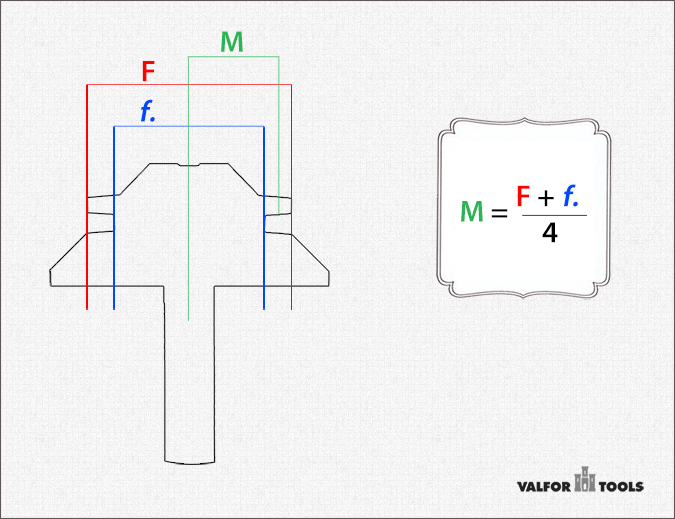
“M” Calculation Diagram

The following examples illustrate the diagram:
| CMT | 855.504.11 | 855.503.11 |
| F | 1.324 | 1.986 |
| f | 1.044 | 1.221 |
| M | 0.592 | 0.802 |
| M rounded | 0.600 | 0.800 |
| FREUD | 99-034 |
| F | 1.900 |
| f | 1.508 |
| M | 0.852 |
| M rounded | 0.850 |
Fine-tuning lock miter bit set-up
The offset (“M”, for the Magic Number) calculation may be subject to small manufacturing tolerances and therefore vary slightly between individual bits of the same manufacturer. It is advisable to calibrate any set-up for a particular Lock Miter Bit with a once-and-for-all test cut.
Therefore, the user is advised once the sweet spot for each particular router bit (where both horizontal and vertical distances to the fence and the table respectively are equal) is found, to note the exact value for future reference.
A good starting point is that, for the smaller Lock Miter Bits, this vertical setting is halfway the small flat end of the finger, and for the larger ones, in the top corner.
Once the exact spot is found for a particular bit, future test cuts will not be necessary.


